Howard Liles, Morris Huang, Jayme Caspall, Stephen Sprigle
Center for Assistive Technology & Environmental Access, Georgia Institute of Technology, Atlanta, GA
ABSTRACT
A wheelchair-propelling robot has been developed to measure the efficiency of manual wheelchairs. The use of a robot has certain advantages over human operators with respect to the repeatability and quantity of measurements possible. The proposed robot can propel a wheelchair according to pre-programmed accelerations and velocities and measures the forces required to achieve these maneuvers. By comparing the kinetic energy of the wheelchair to the work required to propel the wheelchair, mechanical efficiencies can be calculated and compared.
BACKGROUND
Motivation
Multiple factors influence the extent to which manual wheelchairs (MWCs) meet the needs of individual users. During movement in a wheelchair, the ease of control and maneuverability influences overall mobility, and thus the quality of life for wheelchair users. From a mechanical design standpoint, the major factor influencing wheelchair control and maneuverability is the mechanical efficiency of the wheelchair system, which can vary depending on the wheelchair design and configuration (Van der Woude 1988, Van der Woude 1988). When using a less efficient wheelchair, an individual will need to exert increased instantaneous force and total effort for accomplishing their desired travel. This leads to increased fatigue and elevates the potential for injury in the upper extremities (Boninger 2003, Van der Woude 2001).
These issues have motivated research targeting improved wheelchair propulsion, largely investigating steady-state biomechanical efficiency in linear propulsion (Bednarczyk 1995, Beekman 1999). However, the field has yet to directly measure the mechanical efficiency of different MWCs and configurations during curvilinear propulsion. Achieving an effective means of measuring mechanical efficiency will ultimately empower wheelchair users to make equipment selections based upon scientific knowledge.
DESIGN CRITERIA
The Anatomical Model Propulsion System (AMPS) is a robot developed to reliably maneuver MWCs to for mechanical efficiency measurement without the confounding variables of human trials. To meet this objective, the AMPS was designed to propel a MWC through maneuvers that reflect everyday wheelchair usage while measuring the work input and wheelchair kinematics required for mechanical efficiency calculation.
The following design criteria for the AMPS were defined: (1) the system should impart loads onto the wheels, axles, frame and upholstery of wheelchairs in a manner consistent with human operators; (2) it must propel the wheelchair in curvilinear maneuvers pertinent to broad characterization of human MWC performance; (3) the measurement instrumentation should be compatible with most commercially available wheelchairs; (4) data collection must measure the system input work and resultant kinetic energy during freewheeling maneuvers; (5) the equipment should have minimal influence on the overall system mass and inertia; (6) the system should offer an acceptable precision of measurement defined as a coefficient of variation <15% with a goal of <10%; (7) it must be designed with materials and processes that are readily available in order to allow system replication.
The AMPS aims to meet these design criteria via three primary subsystems: the anthropomorphic structure, the propulsion system, and the data acquisition system.
SYSTEM DESIGN AND RATIONALE
Anthropomorphic Design
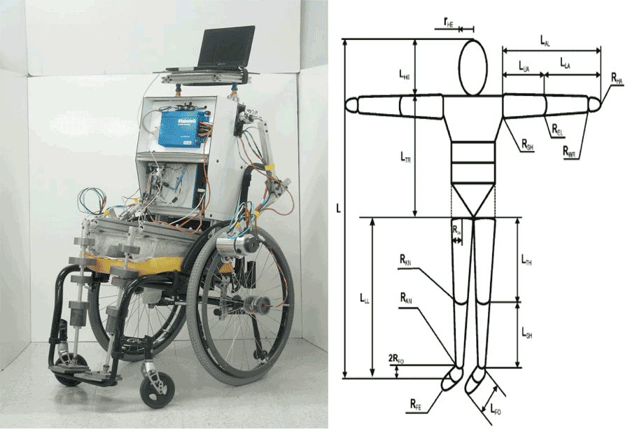 Figure 1 : (Left) Anatomical Model Propulsion System (Right) 16 segment human body model (Nikolova 2007)
 The AMPS (Figure 1) was designed to reflect the body segment parameters of an American male at the 50th percentile in height and 95th percentile in mass. ISO 7176-11 and the Hybrid III ATD were used to define segment mass and lengths.
The size and weight specifications are utilized to capture the inertia of an occupied wheelchair and the interaction between the occupant and the wheelchair. This interaction primarily consists of the user’s loadings on the frame joints, the drive wheels and bearings, and the caster wheels and bearings. Matching the inertia and mass of the human user is vital, given that the average user dominates the system, weighing approximately five times the wheelchair.
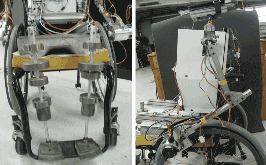 Figure 2: Anthropomorphic AMPS leg and arm structure
The structure of the AMPS closely mimics the anthropomorphic characteristics of an average human. The torso structure is composed of an aluminum frame that houses the batteries which power the AMPS, approximating upper body mass. A concrete mold shaped to approximate the mass and profile of the human posterior supports the torso structure. This mold connects to two aluminum rods which serve as the lower legs. Weights are affixed along the length of these rods to mimic the mass distribution of the lower legs and feet. The arms are attached to the upper torso via a ball joint and are composed of aluminum tubing. The ends of the arms are each attached to custom housings which contain a motor that propels the AMPS. The ball joints provide a significant range of adjustability for the positioning of the arms on various MWCs.
Propulsion Control
The AMPS propulsion system design was influenced by the specifications requiring a driving mechanism with realistic static and dynamic loading, compatibility with commercial wheelchairs, and minimal changes to wheelchair mass and inertia. Based on these requirements, the design features of tangential force drive, dedicated pushrim interfacing, and high-torque DC motors were selected.
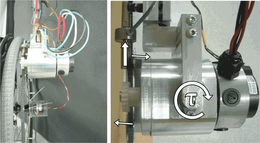 Figure 3 : Propulsion system rack and pinion interface
Manual wheelchairs are conventionally propelled by applying tangential force to pushrims mounted on the drive wheels. Therefore to execute canonical free-wheeling maneuvers, the logical approach is to have the AMPS propulsion system apply tangential force to each wheel rim. Additionally, the system must be capable of differential drive so as to enable turning, as well as have bidirectional drive to allow for motion in both forward and rearward directions. These maneuverability objectives led to the selection of a system where a DC motor is mounted at each pushrim and interfaced via a rack and pinion (Figure 3). Independent control of two DC motors enables turning and bidirectional motion, and the proximal motor mounting to the drive wheel offers the simplest transmission that still propagates the reaction forces to the shoulder joints.
To accommodate the variety of MWC pushrim styles, a dedicated pushrim that can be attached to all wheelchairs during testing was designed. This design offered a standard interface and thus a more consistent force input. The pertinent design constraint for a dedicated AMPS pushrim was to ensure its overall mass and rotational inertia was similar to existing pushrim designs.
The traditional tubular pushrim is replaced by a custom-made PVC ring gear of similar mass. The nylon pinion gear is mounted on the motor shaft and engages the ring gear. The AMPS targets its initial design around the common 18mm pushrim and is compatible with the universal pushrim anchors.
The selection of DC motors as the driving mechanism stemmed from the criteria of bidirectional motion. Literature sources indicated that the maximum tangential pushrim force applied during typical steady-state propulsion (~0.75m/s) is less than 100N (22.5 lbf), and averages at 81N (18.2 lbf) (Robertson 1996). Selection of an appropriate high-torque DC motor can be based on matching the motor’s peak efficiency torque to the nominal 81N, while assuming a pinion gear pitch diameter of 1.25-in. Additionally, the motor max RPM had to achieve a minimal 0.75m/s tangential velocity on the pinion gear during peak efficiency.
Based on the requisite torque of 1.3Nm and and speed of 4511-rev/min, a pair of A28-150 Ampflow motors were chosen to provide propulsion to the wheelchair, with one for each drive wheel. The motors are contained within custom housing fixtures that enable them to interface with a load cell sensor bracket. This bracket contains a force sensing load cell and a pivot axis for the motor, which work in conjunction to enable direct measurement of the tangential force applied to the pushrim. The motors are also directly attached to the AMPS arms so that propulsion reactions propogate to the shoulder joint (Figure 3). These mechanical features allow realistic loading to be achieved, as well as widespread adaptability for a multitude of MWC designs.
The actual propulsion of the AMPS is controlled by a Roboteq motor controller. This controller is supplied power by a set of four 12 volt batteries and also provides power to the motors. These internal batteries enable the AMPS to maneuver through a variety of environments without the need to connect to a local power source. This motor controller incorporates PID parameters and executes the closed loop control of the motor system.
Data Acquisition
The AMPS incorporates a data acquisition system along with multiple sensors to conduct measurements that are used to calculate the input and output energy of the system. At a minimum, the AMPS should detect the same performance differences discernible to humans amongst various MWCs.
A NI USB-6341 data acquisition system (DAQ) is controlled by computer through a visual interface and is used to record data from the wheel encoders, current sensors, and load cells. It also sends analog voltage command signals to a Roboteq motor controller. The DAQ system is powered by a lithium-ion battery that is independent of the batteries supplying power to the AMPS propulsion subsystem.
Two ACS758xCB current sensors are integrated into the circuit powering the drive motors by directly connecting to the motor power cables. Within this circuit, the sensors monitor the current flowing into the motor.
A pair of Omega LCFA-50 load cells are mounted onto a bracket connected to the motor housing unit. During propulsion, the AMPS applies a force that can be partitioned into a tangential (propulsive) and normal (frictional) component relative to the pushrim. The load cell bracket is configured so that it measures the tangential component of the input force (Figure 3 ).
The AMPS incorporates a pair of M-260 Accu-Coder axle mounted encoders, each attached to the central axle of a drive wheel via a custom housing. These 2540 count encoders determine drive wheel motion by angular position measurement. Using the known motion of the drive wheels with the geometry of the wheelchair, the full kinematics of the system can be derived for kinetic energy calculations (Medola 2013).
AMPS CALIBRATION AND VALIDATION
Component Level Calibration
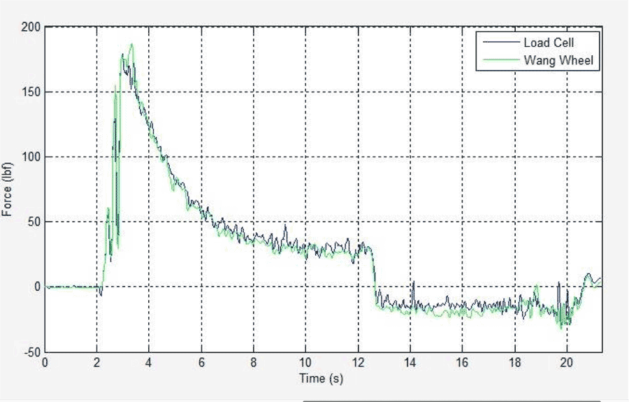 Figure 4 : Left Arm load cell validation data
The force sensing load cells were calibrated in-situ with the instrumented load cell bracket mounted to a custom wheel for measuring propulsive forces. This wheel (Limroongreungrat 2009) incorporates a JR3 force transducer into the pushrim with a solid ring gear attachment and had been pre-calibrated using precision weights. Figure 4 illustrates the close correlation of the force transducer and load cell after calibration.
The current sensors were calibrated independently by loading the motors with a known torque and calibrating the measured output accordingly.
System level Validation:
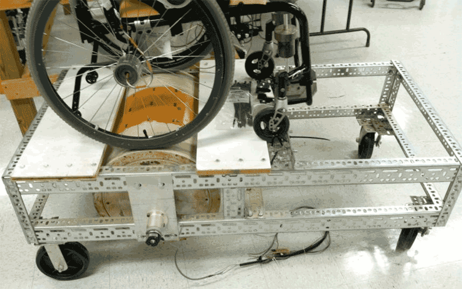 Figure 5 : Dynamometer designed to evaluate AMPS
A dynamometer (dyno) was created to provide a stationary platform for testing the AMPS drive system (Figure 5 ). The dyno consists of a massive drum that is attached to a stationary framework. The drum axle is fitted with a digital, optical, quadrature encoder that provides very precise measurements of the rotation angle. The AMPS is fixed to the frame with the drive wheels in contact with the dyno drum (Figure 5). Friction between the wheels and the drum provides the motivating force for the dyno drum, as well as the inertial reaction for the motors that drive the pushrims of the drive wheels. The AMPS-occupied wheelchair weighs about 250 pounds (115kg). The rotational inertia of the dynamometer was matched to the associated translational inertia of this mass in overground motion, yielding an effective mass of 287 pounds (130 kg). The ratio of the effective dyno mass to AMPS-wheelchair mass is about 1.13, a close agreement of inertias that demonstrate the dynamometer is a stationary platform that properly models the free-wheeling response of the AMPS-occupied wheelchair. This is particularly important during development of periodical propulsion strokes since free-wheeling and coast down must be properly modeled.
The AMPS was also validated by performing maneuvers on the ground. The AMPS was loaded onto a Quickie GT MWC with 24” diameter, spoked, pneumatic tires. The selected maneuver incorporated a straight run that ramped up to a steady state speed within 2.5 seconds, held this speed for 5 seconds and then ramped down to a stop within 2.5 seconds. This maneuver was conducted at a “fast” speed of 2 m/s to stress the capabilities of the system. The maneuver was conducted ten times while measuring wheel velocity, current, and force data, and assessed for repeatability using the coefficient of variation (CV).
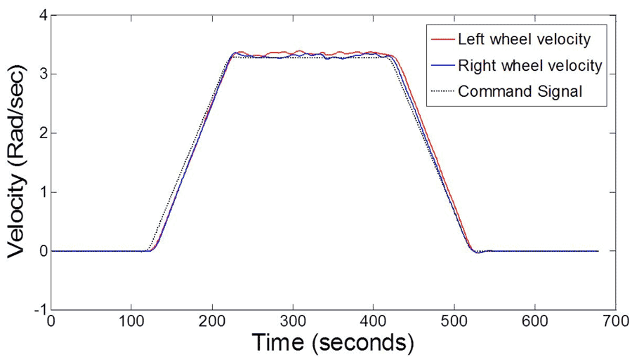 Figure 6 : Velocity Profile at 2m/s (3.28 rad/sec)
Control system accuracy was characterized by comparing the programmed velocity profile to the measured velocity profile and computing the error between the two waveforms every 0.5 seconds (Figure 6 ). A maximum average percentage error and CV for the velocity profile was 2% and 0.94%, respectively.
To characterize the current and force data, peak values during the acceleration and deceleration phases of the maneuver and the average values during the steady-state phase were determined. For DC motors, the motor current is proportional to their torque. Thus, the torque is calculated based on this current. The load cell force is used to also calculate a torque. These two independent measurements provide a redundant calculation of the torque to further enhance the credibility of the data. The maximum CV of the current-based torque was calculated at 7%. The maximum CV of the force-based torque was calculated at 16.8% for the acceleration and deceleration phases. The steady state CV for the force-based torque was much higher for the steady-state portion of the manuever. However, this measure is skewed due to the low average force required to overcome the resistive losses during steady state propulsion.
CONCLUSION
The AMPS was developed as a robotic measurement system to quantify the mechanical efficiency of the entire wheelchair system. The system has been validated to repeatably and accurately record velocity, force, and current data, which can be ultimately used to evaluate MWC mechnical efficiency.
REFERENCES
Bednarczyk, J. H., & Sanderson, D. J. (1995). Limitations of kinematics in the assessment of wheelchair propulsion in adults and children with spinal cord injury. Physical therapy, 75(4), 281-289.
Beekman, C. E., Miller-Porter, L., & Schoneberger, M. (1999). Energy cost of propulsion in standard and ultralight wheelchairs in people with spinal cord injuries. Physical Therapy, 79(2), 146-158.
Boninger, et. al, (2003). Shoulder magnetic resonance imaging abnormalities, wheelchair propulsion, and gender. Archives of physical medicine and rehabilitation, 84(11), 1615-1620.
Limroongreungrat, W., Wang, Y. T., Chang, L. S., Geil, M. D., & Johnson, J. T. (2009). An instrumented wheel system for measuring 3-D pushrim kinetics during racing wheelchair propulsion. Research in Sports Medicine, 17(3), 182-194.
Medola, F., Dao, P., Caspall, J., & Sprigle, S. (2013). Partitioning Kinetic Energy during Freewheeling Wheelchair Maneuvers.
Nikolova, G. S., & Toshev, Y. E. (2007). Estimation of male and female body segment parameters of the Bulgarian population using a 16-segmental mathematical model. Journal of biomechanics, 40(16), 3700-3707.
Robertson, R. N., Boninger, M. L., Cooper, R. A., & Shimada, S. D. (1996). Pushrim forces and joint kinetics during wheelchair propulsion. Archives of physical medicine and rehabilitation, 77(9), 856-864.
Van der Woude, L. H. V., et. al, (1988). Wheelchair racing: effects of rim diameter and speed on physiology and technique. Med Sci Sports Exerc, 20(5), 492-500.
Van der Woude, L. H. V., Veeger, H. E. J., Dallmeijer, A. J., Janssen, T. W. J., & Rozendaal, L. A. (2001). Biomechanics and physiology in active manual wheelchair propulsion. Medical engineering & physics, 23(10), 713-733.
Van der Woude, L. H., et. al, A. P. (1988). Manual wheelchair propulsion: effects of power output on physiology and technique. Medicine and science in sports and exercise, 20(1), 70.
ACKNOWLEDGEMENTS
The authors would like to acknowledge the support of Phuc Dao and the REAR Lab in the completion and development of this work.
Audio Version PDF Version